|
ClearCore Library
|
Loading...
Searching...
No Matches
|
ClearCore Library
|
ClearCore digital output connector class.
This manages a digital output connector on the ClearCore board. This connector can also be configured as a digital input.
The following connector instances support digital output functionality:
For more detailed information on the ClearCore Connector interface, check out the ClearCore Connector System informational page.
ClearCore digital output connector class. More...
#include <DigitalInOut.h>
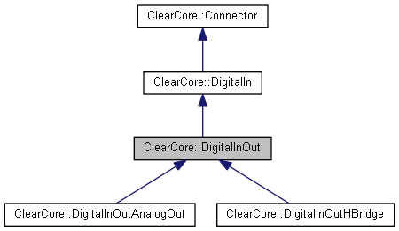
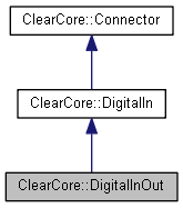
 Inheritance diagram for ClearCore::DigitalInOut: Collaboration diagram for ClearCore::DigitalInOut:
Public Member Functions | |
| virtual ConnectorModes | Mode () override |
| Get the connector's operational mode. | |
| virtual bool | Mode (ConnectorModes newMode) override |
| Set the connector's operational mode. | |
| Connector::ConnectorTypes | Type () override |
| Get connector type. | |
| bool | IsWritable () override |
| Get R/W status of the connector. | |
| int16_t | State () override |
| Get the connector's last majority-filtered sampled value. | |
| bool | State (int16_t newState) override |
| Set the output state of the connector. | |
| bool | IsInHwFault () override |
| Get whether the connector is in a hardware fault state. | |
| void | OutputPulsesStart (uint32_t onTime, uint32_t offTime, uint16_t pulseCount=0, bool blockUntilDone=false) |
| Start an output pulse. | |
| void | OutputPulsesStop (bool stopImmediately=true) |
| Stop an output pulse. | |
| volatile const bool & | OutputPulsesActive () |
| Check the output pulse state. | |
| bool | PwmDuty (uint8_t newDuty) |
| Set the PWM duty on the I/O pin. | |
| Public Member Functions inherited from ClearCore::DigitalIn | |
| void | FilterLength (uint16_t length, FilterUnits units=FILTER_UNIT_SAMPLES) |
| Set the connector's digital transition filter length. The default digital filter length for digital input connectors is 3 samples. | |
| uint16_t | FilterLength () |
| Get the connector's digital filter length in samples. The default is 3 samples. | |
| bool | InputRisen () |
| Clear on read accessor for this connector's rising input state. | |
| bool | InputFallen () |
| Clear on read accessor for this connector's falling input state. | |
| bool | InterruptHandlerSet (voidFuncPtr callback=nullptr, InputManager::InterruptTrigger trigger=InputManager::InterruptTrigger::RISING, bool enable=true) |
| Register the interrupt service routine to be triggered when the given input state condition is met on this connector. | |
| void | InterruptEnable (bool enable) |
| Enable or disable the interrupt on this connector. | |
| Public Member Functions inherited from ClearCore::Connector | |
| void | Reinitialize () |
| Reinitialize this connector to the power-up state. | |
| int32_t | ConnectorIndex () |
| Accessor for the bit index of this connector in the input register. | |
| uint32_t | InputRegMask () |
| Get a bit mask representing this connector. | |
Additional Inherited Members | |
| Public Types inherited from ClearCore::DigitalIn | |
| enum | FilterUnits { FILTER_UNIT_MS , FILTER_UNIT_SAMPLES } |
| Units for the digital filter length. More... | |
| Public Types inherited from ClearCore::Connector | |
| enum | ConnectorModes { INVALID_NONE , INPUT_ANALOG , INPUT_DIGITAL , OUTPUT_ANALOG , OUTPUT_DIGITAL , OUTPUT_H_BRIDGE , OUTPUT_PWM , OUTPUT_TONE , OUTPUT_WAVE , CPM_MODE_A_DIRECT_B_DIRECT , CPM_MODE_STEP_AND_DIR , CPM_MODE_A_DIRECT_B_PWM , CPM_MODE_A_PWM_B_PWM , TTL , RS232 , SPI , CCIO , USB_CDC } |
| All possible operational modes for a connector. More... | |
| enum | ConnectorTypes { DIGITAL_IN_TYPE , DIGITAL_IN_OUT_TYPE , SHIFT_REG_TYPE , ANALOG_IN_DIGITAL_IN_TYPE , ANALOG_OUT_DIGITAL_IN_OUT_TYPE , H_BRIDGE_TYPE , CPM_TYPE , SERIAL_TYPE , SERIAL_USB_TYPE , CCIO_DIGITAL_IN_OUT_TYPE } |
| The different types of ClearCore connectors. More... | |
|
inlineoverridevirtual |
Get whether the connector is in a hardware fault state.
Implements ClearCore::Connector.
|
inlineoverridevirtual |
Get R/W status of the connector.
Reimplemented from ClearCore::DigitalIn.
Reimplemented in ClearCore::DigitalInOutAnalogOut, and ClearCore::DigitalInOutHBridge.
|
inlineoverridevirtual |
Get the connector's operational mode.
Reimplemented from ClearCore::DigitalIn.
Reimplemented in ClearCore::DigitalInOutAnalogOut, and ClearCore::DigitalInOutHBridge.
|
overridevirtual |
Set the connector's operational mode.
| [in] | newMode | The new mode to be set. The valid modes for this connector type are: |
Reimplemented from ClearCore::DigitalIn.
Reimplemented in ClearCore::DigitalInOutAnalogOut, and ClearCore::DigitalInOutHBridge.
|
inline |
Check the output pulse state.
This allows you to see if there is a currently running pulse on this output.
| void ClearCore::DigitalInOut::OutputPulsesStart | ( | uint32_t | onTime, |
| uint32_t | offTime, | ||
| uint16_t | pulseCount = 0, |
||
| bool | blockUntilDone = false |
||
| ) |
Start an output pulse.
This allows you to start a pulse on the output that is on for onTime milliseconds and off for offTime milliseconds and will stop after pulseCount cycles. A pulseCount of 0 will cause the pulse to run endlessly. If a pulse is already running, calling this will allow you to override the previous pulse (after the next change in state).
| [in] | onTime | The amount of time the input will be held on [ms]. |
| [in] | offTime | The amount of time the input will be held off [ms]. |
| [in] | pulseCount | (optional) The amount of cycles the pulse will run for. Default: 0 (pulse runs endlessly). |
| [in] | blockUntilDone | (optional) If true, the function call will wait until pulseCount pulses have been sent before returning. Default: false. |
| void ClearCore::DigitalInOut::OutputPulsesStop | ( | bool | stopImmediately = true | ) |
Stop an output pulse.
This allows you to stop the currently running pulse on this output. The output will always be set to FALSE after canceling a pulse.
| [in] | stopImmediately | (optional) If true, the output pulses will be stopped immediately; if false, any active pulse will be completed first. Default: true. |
| bool ClearCore::DigitalInOut::PwmDuty | ( | uint8_t | newDuty | ) |
Set the PWM duty on the I/O pin.
The pin must be in OUTPUT_PWM mode, or else nothing will happen and this function will return false.
| [in] | newDuty | The PWM duty cycle for the pin, from 0 to 255 (UINT8_MAX). |
|
overridevirtual |
Get the connector's last majority-filtered sampled value.
Reimplemented from ClearCore::DigitalIn.
Reimplemented in ClearCore::DigitalInOutAnalogOut, and ClearCore::DigitalInOutHBridge.
|
overridevirtual |
Set the output state of the connector.
This allows you to change the output value of the connector item.
| [in] | newState | The value to be output. |
Implements ClearCore::Connector.
Reimplemented in ClearCore::DigitalInOutAnalogOut, and ClearCore::DigitalInOutHBridge.
|
inlineoverridevirtual |
Get connector type.
Reimplemented from ClearCore::DigitalIn.
Reimplemented in ClearCore::DigitalInOutAnalogOut, and ClearCore::DigitalInOutHBridge.